
Ultherapy Joule Settings: A Practical Energy-Safety Guide for 1.5–4.5 mm Depths
Micro-focused ultrasound with visualization (MFU-V, Ultherapy) remains a core non-surgical tightening platform as global demand for face and neck lifting continues to grow. Recent clinical reviews report typical per-shot energy ranges of about 0.25–1.2…
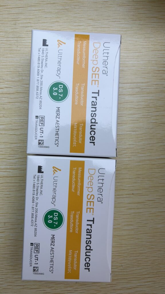
Micro-focused ultrasound with visualization (MFU-V, Ultherapy) remains a core non-surgical tightening platform as global demand for face and neck lifting continues to grow. Recent clinical reviews report typical per-shot energy ranges of about 0.25–1.2 J, with most treatment parameters clustering between 0.3–0.9 J for facial indications. Within this band, energy increments from 0.15 J to about 1.05 J can be scaled safely when clinicians adjust for transducer depth (1.5, 3.0, 4.5 mm), anatomic site, patient tolerance, and total-line density, following manufacturer line patterns and regional regulatory guidance.
Against this backdrop, a structured understanding of the 0.15–1.05 J window across 1.5 mm, 3.0 mm, and 4.5 mm depths helps practitioners standardize protocols, train new operators, and optimize consumable usage without compromising patient safety. This article translates those Joule values into a practical, decision-grade framework for clinics standardizing Ultherapy protocols, managing workflows, and evaluating new vs certified pre-owned (CPO) Ulthera systems.
Core Principles of Ultherapy TCP Energy
The Ulthera System combines a control unit, DeepSEE handpiece, and interchangeable image/treat transducers that define the treatment depth, frequency, and scan length. Typical transducers include 1.5 mm (10 MHz), 3.0 mm (7 MHz), and 4.5 mm (4 or 7 MHz) modules, with scan lengths up to 25 mm.
Ultherapy uses micro-focused ultrasound bursts to create thermal coagulation points (TCPs)—discrete 1 mm³ lesions—placed in linear rows at fixed depths without disrupting the epidermis. Each burst of energy forms a line of TCPs, spaced at programmable intervals (commonly 1–1.5 mm) oriented along the treatment line. When discussing “0.15–1.05 J” in Ultherapy, the industry refers to the energy delivered per individual TCP, not per treatment line. This allows fine-grained scaling of dose intensity by depth, indication, and skin thickness, reaching targeted temperatures around 60–70°C in the focal zone to trigger neocollagenesis.
Technical and Operational Pain Points in Energy Scaling
A lack of clarity regarding shot-level energy vs line-level energy frequently creates clinical challenges. Many clinics do not clearly distinguish between shot-level energy (per TCP) and line-level energy (typically 17 TCPs over a 25 mm line). Without a shared language, senior practitioners might think in joules per line while junior operators look at device screens calibrated per TCP, producing inconsistent dosing across the practice.
Depth-specific tissue responses are also frequently underappreciated. At 4.5 mm, energy targets the SMAS and deep fibromuscular layers, where higher joule settings can be beneficial but carry a higher risk of discomfort and structural injury if overlapped excessively. At 1.5 mm, the epidermal and superficial dermal safety margin becomes critical. Running high-energy protocols on thin skin increases erythema, edema, or transient dysesthesia events.
Furthermore, when the supply of specific transducers becomes tight, some clinics react by shifting protocols toward doing more with fewer lines—escalating energy per TCP rather than maintaining proper line count and coverage. Escalating from 0.3 J to 1.0 J without adjusting spacing or passes provokes pain spikes and uneven outcomes.
Finally, documentation and training often lag behind protocol evolution. As newer Ultherapy PRIME systems expand clinical options, centers must constantly update their SOPs to match current clinical evidence, protecting the clinic against medico-legal risks during staff turnover.
MFU-V System Comparison and Energy Matrix
The following table provides a strategic clinical view comparing authentic Ultherapy/Ultherapy PRIME parameters against typical non-visualized HIFU devices and multi-brand hybrid platforms across core tissue depths.
| Dimension | Ultherapy / Ultherapy PRIME (MFU-V) | Non-Visualized HIFU Face Devices | Hybrid Energy Platforms |
| Depth Options | 1.5 / 3.0 / 4.5 mm fixed focal depths | Common 1.5 / 3.0 / 4.5 mm options | 1.5–4.5 mm depending on system modules |
| Single TCP Energy Range | Typical range 0.25–1.2 J; main protocols at 0.3–0.9 J | Stated 0.1–2.0 J; practical usage 0.2–0.8 J | Approximately 0.2–1.0 J based on indication |
| 0.15–1.05 J Coverage | Fully calibrated across complete clinical band | Variable accuracy at extreme low/high ends | Requires independent calibration per handpiece |
| Imaging & Visualization | Real-time ultrasound visualization up to 8 mm | No real-time imaging; relies on landmarks | Basic B-mode or surface navigation only |
| Primary Utility | Face/neck non-surgical lifting & wrinkle reduction | Entry-level skin tightening and contouring | Combined multi-modality lifting protocols |
| Consumable Ecosystem | Genuine transducers & certified B2B supply pipelines | OEM and aftermarket third-party variations | Complex multi-brand tip inventory management |
Depth-Specific Energy Logic Across the 0.15–1.05 J Band
1.5 mm Depth: Superficial Dermis and Safety Margins
The 10 MHz 1.5 mm transducer targets the shallow dermal matrix and fine lines. Unit TCP energy typically ranges around 0.15–0.4 J to minimize epidermal thermal stress. In highly sensitive or thin-skin regions such as the periorbital zone, protocols often favor lower energies starting at 0.15–0.2 J, adjusting upward based on real-time tissue response and patient comfort. The system constrains absolute maximum output to under 1.5 J at this frequency to preserve superficial tissue safety.
3.0 mm Depth: The Dermal Reticular and Mid-Dermal Workhorse
Operating at 7 MHz, the 3.0 mm depth serves as the primary layer for skin tightening and structural collagen remodeling. TCP energies commonly span 0.25–0.8 J, balancing deep collagen targeting with manageable thermal loads. For mild-to-moderate laxity in the midface and jawline, standard protocols cluster between 0.3–0.6 J, paired with appropriate line density and line spacing to achieve gradual tissue contraction.
4.5 mm Depth: SMAS and Deep Musculoaponeurotic Targeting
The 4.5 mm depth utilizes 4 or 7 MHz frequencies to reach the deep SMAS layer and platysma. Energy settings scale between 0.4–1.05 J based on tissue thickness and anatomical location. High-end energies approaching 1.0–1.05 J are generally reserved for thicker submental and lower-face areas, where robust deep-layer thermal coagulation points are required. Operators utilize real-time imaging to confirm proper transducer coupling, avoiding underlying bone structure or major vascular pathways.
Actionable Energy and Line Prescription Examples
For the Jawline and Neck: Use a 4.5 mm transducer set to 0.6–0.9 J, delivering 17 TCPs per line. Apply lines along designated anatomical grids using a dual-layer, cross-hatched pattern to maximize tightening along the vector of laxity.
For the Mid and Lower Face: Utilize a 3.0 mm transducer set to 0.3–0.6 J, planning 4 to 6 horizontal rows per zone. Focus energy delivery directly on the tissue adjacent to the nasolabial folds and marionette lines to address gravity-induced descent.
For Periorbital and Fine Lines: Apply a 1.5 mm transducer set to 0.2–0.3 J. Reduce the structural line spacing slightly to target dense superficial wrinkling, while strictly avoiding overlapping lines in a triple-layer pattern.
Six Steps to Safely Scale Ultherapy Energy
Step 1: Define Clinical and Layer Targets Establish whether the primary treatment objective is deep structural lifting (SMAS), mid-dermal tightening (reticular dermis), or superficial texturing (upper dermis), assigning priority to the 4.5 mm, 3.0 mm, or 1.5 mm transducers respectively.
Step 2: Establish a Baseline Energy Value Begin new treatments or operator sessions using conservative mid-range parameters, such as 0.25–0.4 J depending on the selected depth. Evaluate initial patient feedback, immediate erythema, and transient localized edema within the first 1 to 2 lines before scaling upward.
Step 3: Grade Energy by Zone and Tissue Thickness Customize energy parameters across anatomical boundaries. Advance toward 0.75–1.0 J at the 4.5 mm depth in dense submental zones, while capping thinner zygomatic and periorbital fields to 0.15–0.4 J to protect delicate structures.
Step 4: Standardize Grid and Line Density Maintain fixed line parameters and grid configurations. Rely on incremental adjustments to single TCP energy rather than making ad-hoc additions to line counts, preventing localized heat accumulation.
Step 5: Record Three-Dimensional Patient Data Document patient profiles by tracking treatment zone, line count, and specific Joule settings (e.g., tracking tolerance at 0.3 J versus 0.6 J). This data forms an individualized map for multi-session maintenance plans.
Step 6: Coordinate Energy Strategy with Consumable Supply Align annual clinical volume forecasts with transducer procurement. Maintaining a reliable inventory of 1.5 mm, 3.0 mm, and 4.5 mm modules ensures the clinical team does not resort to inflating energy settings on an improper depth module due to a shortage of the correct transducer. Sourcing channels like ALLWILL assist clinics in establishing stable inventory cycles, bridging the gap between clinical protocol design and backend asset availability.
Strategic Asset Management and Revenue Optimization
Ultherapy functions as a premium, non-surgical treatment that supports high revenue per session but requires precise resource scheduling to balance procedure times and consumable wear. The relationship between energy per TCP, line density, and total lines delivered directly governs treatment duration and transducer lifespan—the two primary components determining clinic return on investment (ROI).
Using standardized, mid-to-high energy lines maintains predictable patient outcomes and clinical value. Conversely, lowering energy to the bottom of the 0.15–1.05 J spectrum to maximize patient comfort can sometimes increase the necessity for follow-up sessions. This shifts the practice model toward a volume-driven approach, highlighting the value of system uptime and equipment longevity. In this environment, a thoroughly vetted Certified Pre-Owned (CPO) system can deliver performance metrics comparable to new hardware.
Biomedical Engineering Maintenance Checklist for Energy Consistency
To ensure the system delivers accurate acoustic energy across all depths, clinical engineering teams and device owners should utilize the following preventative maintenance checklist.
-
Verify Regulatory Markings and Lineage: Confirm device labeling and documentation align with applicable regional regulatory frameworks, such as FDA 510(k) clearances or CE marks. Maintain original Instructions for Use (IFU) and verified software versions to ensure calibrated energy delivery.
-
Inventory Transducer Lifecycle Data: Document all active 1.5 mm, 3.0 mm, and 4.5 mm transducers. Track serial numbers, manufacturing dates, and remaining shot capacities. For CPO hardware, require written logs of previous usage profiles.
-
Audit Calibration and Energy Limits: Confirm peak acoustic energy thresholds stay within manufacturer parameters, keeping maximum energy per pulse below 3 J for 4–7 MHz modules and under 1.5 J for 10 MHz modules. Establish periodic testing schedules to verify pulse timing.
-
Inspect Handpiece and Cabling Assemblies: Conduct weekly visual inspections of the DeepSEE handpiece and connected cables for signs of wear, insulation breakdown, or fluid ingress. Verify all integrated control buttons and emergency stop mechanisms respond immediately.
-
Validate Ultrasound Imaging Quality: Use a test phantom to confirm clear visualization up to the standard 8 mm depth. Ensure the B-mode image clearly differentiates tissue interfaces and bone boundaries without artifact interference.
-
Implement Environmental and Power Safeguards: Position the system within recommended temperature and humidity ranges to avoid thermal scanning shut-downs. Connect the console to an Uninterruptible Power Supply (UPS) to protect sensitive digital tracking components from power fluctuations.
-
Enforce Approved Cleaning Protocols: Disinfect transducer faces and handpiece surfaces according to manufacturer guidelines, avoiding abrasive chemicals or complete fluid immersion that could compromise acoustic membranes. Inspect membranes daily for micro-fissures.
-
Log Incidents and Calibrations: Keep a comprehensive service log detailing all preventative maintenance actions, part replacements, and clinical alerts to support quality assurance tracking across multi-site clinic networks.
Compliance, Safety, and Asset Procurement
The Ulthera System IFU stipulates that only properly trained medical professionals should operate the device. Improper handling can cause thermal burns, temporary motor or sensory nerve issues, or bruising. Side effects noted in clinical studies include transient erythema, mild edema, localized welting, and minor altered sensation, with most cases resolving within days or weeks.
From a compliance standpoint, energy delivery is contraindicated over the thyroid gland, major superficial blood vessels, and breast implants. Clinical safety parameters have not been established for pregnant patients or individuals with severe systemic diseases, requiring sound practitioner judgment.
When purchasing equipment, acquisition teams should avoid units with unverified service backgrounds or expired transducer sets. Sourcing through structured entities like ALLWILL offers access to comprehensive inspection logs, documented calibration cycles, and structured warranties, allowing clinics to confidently align asset acquisition with long-term clinical usage.
Operational Multi-Modality Scenarios
Scenario 1: Specialized Single-Clinic Optimization
Traditional Approach: Relying on legacy MFU hardware without imaging integration or distinct energy staging. Treatments are often delivered at a uniform face-wide setting of 0.3–0.4 J, leading to inconsistent lifting along the jawline. Integration Strategy: Deploying upgraded systems with real-time visualization alongside a stratified 0.3–0.9 J depth protocol. By stabilizing transducer acquisition channels through B2B partners like ALLWILL, the facility introduces advanced line-density protocols at a stable operating cost.
Scenario 2: Multi-Site Corporate Standardization
Traditional Approach: Individual regional clinics operate under separate energy protocols based on local operator preference, resulting in non-standardized client data and variable outcomes across the brand. Integration Strategy: Corporate leadership introduces a centralized SOP covering the 0.15–1.05 J energy matrix across specified anatomical depths. This clinical standardization is paired with synchronized supply planning, allowing enterprise-level management of transducer consumption and consistent treatment outcomes.
Scenario 3: High-End Comprehensive Aesthetics Workflow
Traditional Approach: Skin tightening, surface laser retexturing, and deep tissue lifting operate as isolated services without a coordinated timeline, limiting patient outcomes to single-modality effects. Integration Strategy: The medical team builds an integrated annual program. The foundation relies on deep-layer Ultherapy 4.5 mm lifting (0.6–1.0 J), transitions to 3.0 mm mid-dermal targeting (0.3–0.6 J), and concludes with superficial RF or laser treatment. Consumable budgets across diverse platforms are managed through an all-inclusive supply partner, optimizing purchasing workflows.
Frequently Asked Questions
What is a safe starting point between 0.15 J and 1.05 J for facial treatments?
For most facial lifting protocols, a safe starting point involves setting the 3.0 mm transducer to 0.25–0.4 J, adjusting based on patient feedback. The 4.5 mm layer can be initiated at 0.4–0.6 J, while the 1.5 mm superficial transducer is typically kept at 0.15–0.3 J to protect the upper dermal boundaries.
How many thermal coagulation points are created per line, and how does that impact energy calculation?
A standard Ultherapy transducer delivers approximately 17 TCPs along a single 25 mm scan line. The total energy output per line represents the single TCP Joule setting multiplied by 17. Practitioners must manage both single-point Joule values and total line counts to prevent localized thermal cross-over.
What is the target temperature achieved within the 0.15–1.05 J range?
The system creates localized temperatures between 60–70°C at the designated focal depth, which is the optimal range to induce collagen denaturation and subsequent tissue synthesis without causing widespread coagulative necrosis, provided spacing parameters are followed.
How should an operator adjust energy when moving between 1.5 mm, 3.0 mm, and 4.5 mm transducers?
The standard clinical approach uses higher-range energies (0.6–0.9 J) at the 4.5 mm depth to effectively target the dense fibromuscular layers of the SMAS and platysma. As the operator moves superficially to the 3.0 mm depth (the reticular dermis), energy should be systematically scaled down to a moderate range (0.3–0.6 J) to balance structural remodeling with manageable thermal accumulation. Finally, when switching to the 1.5 mm superficial transducer, the operator must lower parameters strictly to 0.15–0.3 J. This step-down logic ensures optimal acoustic power reaches deeper foundational layers while maintaining a stringent safety margin to prevent epidermal thermal stress or transient dysesthesia in shallow tissue boundaries.
Key Takeaways for Practice Managers
-
Standardize Device Metrics: Ensure your entire clinical team explicitly differentiates between single-point TCP energy and total line energy to prevent accidental over-dosing.
-
Prioritize Real-Time Visualization: Always utilize active ultrasound imaging to verify proper transducer coupling, map anatomical boundaries, and protect underlying bone and major vascular paths.
-
Maintain Balanced Inventories: Secure a reliable supply of all three core transducer depths (1.5 mm, 3.0 mm, and 4.5 mm) through verified B2B pipelines like ALLWILL to avoid clinical workarounds or unsafe energy inflation on incorrect modules.
-
Enforce Strict Preventative Maintenance: Adhere to a rigorous clinical engineering checklist—including weekly handpiece inspections, regular calibration audits, and ultrasound image validation—to secure consistent energy delivery and protect clinical ROI.
Related articles
Ultherapy Transducers: What the Probe Record Changes About the PriceBrand and Model Buying Guides Candela GentleMax Pro: Demand, Verification and Cost Before You CommitBrand and Model Buying Guides
 Alma VH1160 Vector Handpiece Code: What the Part Number Tells a BuyerBrand and Model Buying Guides
 DEKA Onda Pro: Investment Case, Verification and Pre-Owned RealityBrand and Model Buying Guides